Friday, May 7, 2010

TEAM J: Paquete Emballeurs


TEAM J: Paquete Emballeurs

Main Design Concept:


The main inspirations that led to our design are human’s hand. Our hands have incredible number of degrees of freedom that handle wrapping with ease. The design is based on the steps that we, as humans, take to wrap a package. Although we are using a high number of degree of freedom, our package wrapper has the potential of perfectly wrapping a package with sufficient testing and calibrations. The design is very robust and it can also handle wrapping packages of various sizes and weights (not just an empty box) because we avoided a design that required lifting the box. The system consists of various sub-systems that help achieve wrapping packages. These sub-systems are the cutter device, a spray adhesive device, the flaps, the grippers, the movable platform and the side rails . Most of the sub-systems overlap at some point during the wrapping process to attain the ultimate goal of wrapping the package. This system uses several flaps, namely: bottom flap, side flaps and roller flaps. These flaps take care of neatly folding all of the sides. 


System Overview:


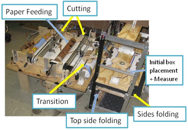
                                                        Figure 1. The Entire System


The machine goes through five major stages in order to properly wrap. These stages are:
 1) Sensing the dimensions of the packages and then feeds paper accordingly.
 2) Cutting the paper. 
 3) Folding three of the sides. 
 4) Grippers grab the package and turns it 90 and then 180 degrees to fold the two uncovered    sides.


SUBSYSTEMS:

1) Rotary Table: the legs of this table have L‐bracket with grippers attached to
it. It is responsible of moving the 3 grippers by 90 and then 180 degrees. This
is a original part of the system because we use the turntable using one motor
to drive the 3 grippers around.


 Figure 2: Rotary table and raised base.


2) Grippers: Two of these grippers are responsible of grabbing a package and orienting it at the desired position for the folding of the remaining two sides. The plan was to use the third gripper to hold the package while taping took place at the opposite side of the package but the role of this grippers changed as we did not need it for the adhesion of the paper. We decided to keep the gripper because it could be used to push the package while the movable platform was carrying a relatively light package. These grippers can automatically adjust to grab a package and fall within the specification provided (Length 5-10’’, Width 3-5’’, Height 1-2.5’).

                                                  
                                             Figure 3: Gripper and its components

3) Side Rails: It moves the roller flap in the y-direction to completely cover 4 sides
of the package. This particular sub-system is innovative because it uses only one
DC motor to drive two rails and moreover the rails are upside down.


Figure 4. This figure shows the CAD model of the Side Rails  


4) Movable platform: The paper is pinched using the bottom flap attached to this platform. In this case, the bottom flap acts as a gripper. Initially we used the solenoids to grip the paper and then move the side rails in the y-direction. Once the paper is pinched using the bottom flap, the movable platform moves in the y direction away from the roll of paper and feeds more paper according to the dimension of the package. We also used this platform to move the package close to the paper cutter to trim the excess paper that resulted when the roller flap folded the paper over the package.


Figure 5. This figure shows the Side Rails and the movable platform


5) Cutter device: It cuts the paper at a fixed location and moves along the x-axis. It cuts both, single and double layer of wrapping paper. The original part of this sub-system is that it gets out of the way of the gripper and it is pretty scary.


Figure 6. This figure shows the cutter device.

6) Spray Adhesive device: This subsystem is responsible of spraying glue to the package and sticking the wrapping paper to the surface of the package. Initially we sorted out ways of affixing the paper to the package that includes spray glue single-sided scotch tape, double sided tape. Spray glue seems to be the best option but we concluded that it was too messy to begin with. Single-sided scotch tape was the best solution as it could be adapted to a solid and robust structure and modify accordingly to the needs. We ended up using the spray adhesive after realizing that the taping device that we develop required too many degrees of freedom and it would required much more machining and time to fully develop it.


Figure 7. This figure shows the spray adhesive mechanism

7) Flaps: There are three types of flaps:
i. Bottom Flap: it is attached to the movable table and it displaces upward to fold the paper from below  (Figure 8A)
ii.  Side Flap: it folds the paper inward to prepare for folding of the other two sides mainly the top and bottom sides (Figure 8B).
iii. Roller Flap: the roller flap is responsible of doing the initial folding displacing in the y-direction once the paper is cut. It is then rotated downward to fold the edge in the z-direction (see Figure 8C ).


 Figure 8A.Figure shows the bottom flap and the movable table 


 Figure 8B. The figure shows the details of the Side Flap


Figure 8C: This figure shows the Roller Flaps.


Team Members and Responsibility:


Lina Gonzalez: Mechanism Design and Fabrication
Severine Coquoz: Control programming and electronics
Siddhartha Vowles:Control programming and electronics
Rahul Bhat: Mechanism Design and Fabrication


Video:

Team C: Team Trash Talkers - Basketball Shooters


Main Design Concept
Our design was quite simple. It was broken up into two main parts. The stationary “base” which houses all of the electronics and the rotating top portion which would house our motor-drive throwing arm, web camera, and hopper. Our machine would start by rotating until a backboard is found and centered in the view of the web camera mounted on top of the dome. When the camera is facing directly toward the backboard, the throwing arm which is situated directly behind the camera will also be facing right towards the backboard. From this position, we will use computer vision to get the distance from our machine to the backboard we are aiming for. From this distance, we will determine with what speed we should shoot the basketball to make it in the hoop.


System Overview 


Figure 1. System Overview
 
  
The design consists of four subsystems, the rotational degree of freedom (DOF), longitudinal DOF, the hopper, and the computer vision (CV).  The rotational degree of freedom consists of the rotating base.  The longitudinal DOF refers to the throwing arm.  The hopper system actuated the basketball distribution to the throwing arm using a servo-motor (range: 0°-180°).  The CV encompassed our backboard tracking as well as our distance sensing.  From the image X, the body, which houses the hopper, CV and throwing arm sits on the rotating base allowing the robot to search for the backboard and fire.


Figure 2. Hopper and throwing arm.

The rotational subsystem allows the robot to travel a full 360° to scan the environment searching for the backboard.  This is controlled by one motor driving one spur gear in small steps.  The steps are required to give the CV program enough time to survey the area.  If the CV doesn’t find the backboard on the first pass, we risk having to wait for another full rotation, so the step timing had to be set and help to a deliberate 250ms.


Figure 3. Gear system connecting the stationary base and rotating top.

In order to have enough power to throw the ball, we needed a high torque 18V drill motor.  Furthermore, because of the speed with which we would be throwing the ball, we were reluctant to use an optical encoder system because we had issues with overshooting specific points and having to compensate.  To ensure a precise and repeatable stopping position, we cut out and reinforced a section of the body to act as a stopper.  We gauged the amount of time we’d supply a duty cycle to the drill motor to avoid driving the motor when we restricted its motion.  We also hollowed out a resting position in the body so we would have a constant trajectory from start to finish. 

After the arm motor completed one shot, breaked, and went back to resting position, we supplied a signal to a servo-motor to allow one ball to roll down the rails and into the throwing cup.  The hopper is housed primarily inside the body to protect the balls from falling out from any outside disturbances, the only place the rails extend out are to place the basketball in the cup.  It was also meant to be a simple and clean looking design.  The system held and distributed two basketballs for each round before having to be reloaded. 


The catapult design is centered on a powerful throwing arm with precise control through a motor driver with feedback from an optical encoder. The arm is used to launch the ball into the hoop. A servo actuated loader feeds each ball individually into the ball holder on the arm. An ultrasonic rangefinder senses the longitudinal distance to the hoop, while the lateral distance from center is manually entered by the user. The entire system is mounted on a ball bearing turntable actuated by a stepper motor with a timing belt to allow accurate aiming at off-center targets.
How it works

The program is organised in a finite state machine structure. The different states are:
- IDLE: All motors off, no action, listening to some prospective orders coming from the PC through the serial communication. This is the default state when the system is started.
- AIM: In this state, the microcontroller is waiting for orders from the PC to turn the base one step left or one step right, until the system is centred and the PC sends the order to go to the next state.
- DISTANCE: In this state, the microcontroller is waiting for the distance data from the PC. Once it gets it, it uses the lookup-table to do a weighted average of the two closes values in the table, and sets the resulting PWM duty-cycle as the throwing speed.
- RELOAD:  A low duty-cycle PWM is given to the throwing arm in the backwards direction to bring it down. Then the servo motor holding the balls in the hopper is actuated briefly to let one ball go down the path to the cup.
- FIRE: The microcontroller sends a PWM to the throwing motor, with the duty-cycle found during the DISTANCE state. The motor is powered for half a second, letting the arm accelerate and hit the stopper.
- BREAK: The microcontroller holds the throwing arm motor-drive in break mode for a second.

The states are executed in the following order:


Figure 4. Flow chart of the PIC program

For the aiming control, we use a proportional feedback from the webcam. The CV program on the PC sends data to the PIC.
To know how fast we have to throw the ball, we use a lookup-table to convert the measured distance into a duty-cycle for the motor of the throwing arm. The CV program on the PC sends the distance value to the PIC.


Team's Responsibility 
 
Zachary Barker / Mechanics
Clive Myrie / Computer Vision
Joel Rey / Microcontroller Programming
Michael Soto / System Integration
  
Video 

link: http://www.youtube.com/watch?v=eu65qvNOWsQ

Team E: Santa's Rapper Mafia

Main Design Concept
Few of the key features of this system are the use of unique foam concept for folding purposes and also the ability of cutting system to cut “cross” shapes.
Using a foam simplifies the folding process by taking advantage of the material property of foam. The first highlight of our system is the foam folding subsystem. If enough force is pressed between the object and the foam, foam will deform and adapt to the shape of the object. The idea was based on an observation that when an object is submerged into a liquid, the object displaces the liquid and hence one is end with an object surrounded by liquid. Nevertheless, the key difference is that foam also presents enough resistance, so that it can deform weak materials in this case paper while it adapts to the shape of stiffer materials in this case the box itself.
The second highlight of the system is capability of cutting paper into cross shaped. Wrapping paper is cut into cross shape to cover the six sides of the box with no excess paper.


System Overview

Figure 1. System Overview
Operation Process:
1. User puts the box at the measurement platform
2. Paper is rolled out and cut into cross or rectangle shaped
3. Transit cut paper to folding subsystem
4. Box gets pushed through foam, fold bottom and sides of box
5. Foam door rotates down and fold top side of box


Subsystems 
    1. Measuring: The user places a random sized box (within the dimensions) at the center of the area that has colored coded lines to align the box. Then, two IR sensors measure box’s width and length.
Figure 2. Measuring System

   
2. Cutting: Gift Wrap paper is rolled out and cut into a rectangle or cross shape according to the dimensions of the box measured from step one.
Figure 3. Cutting System
    3. Transition: Mechanism of wheels transfers cut paper from cutting subsystem to folding subsystem.
Figure 4. Feeding System

    4. Gluing: Glue is sprayed on top of the cut paper, which lays one level below the measuring system that is holding the box on top.
Figure 5. Gluing System

    5. Folding:The Box, which has the cut paper underneath, is pushed down through a layer of thick foam, so the four lateral sides of the box and bottom are glue and wrapped around it. Top side folding: A door rotates down 90 degrees to push the remaining paper onto the top of box to finalize the wrap.

Figure 6. Folding System

Team's Responsibility
Siying(Diana) Hu / Electronics and Control
Zhiwei(Hank) Huang / Mechanics
Chenyue(Melody) Li / Electronics and Control
Mohitdeep Singh / Mechanics

Video