Like most of the other teams, the main focus of our team was making things simple as possible. "Throwing" the ball turned out to be the most intuitive way to shoot a basketball, and the most simple throwing mechanism our team members could think of was a catapult. Having only a single motor involved in the actual shooting process maximized the accuracy.
System Overview

Figure 1. System Overview
The catapult design is centered around a powerful throwing arm with precise control through a motor driver with feedback from an optical encoder. The arm is used to launch the ball into the hoop. A servo actuated loader feeds each ball individually into the ball holder on the arm. An ultrasonic rangefinder senses the longitudinal distance to the hoop, while the lateral distance from center is manually entered by the user. The entire system is mounted on a ball bearing turntable actuated by a stepper motor with a timing belt to allow accurate aiming at off-center targets.
Subsystems

Figure 2. Ultrasonic Range Finder
To find the distance from the launcher to the backboard we used the Maxbotix EZ3 ultrasonic rangefinder. The analog voltage output of the rangefinder is connected to an ADC channel on the PIC, and a lookup table is used to accurately determine the distance in inches to the backboard.
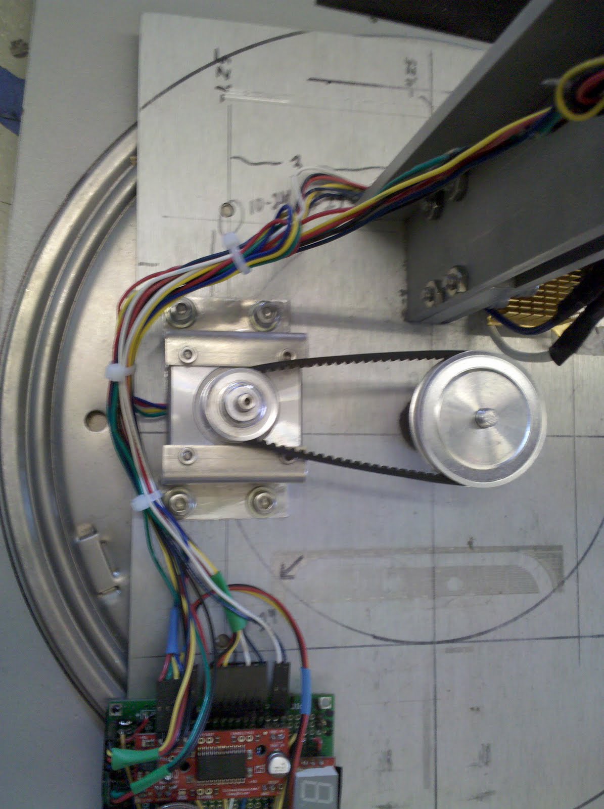
Figure 3. Turn Table
To allow us to aim at targets off of the center-line, all of the subsystems are mounted on top of a turntable. An axle fixed to the base projects through the center of the turntable and is fitted with a timing belt connected to a stepper motor (the SFE stepper). While the stepper is nominally rated at 1.8 degrees/step, the use of 8 part microstepping through the SFE stepper driver allows us to easily and reliably obtain accurate rotation. The stepper driver is interfaced to the PIC through two digital lines, one signaling direction of rotation and the other pulsed to step the motor. Power is provided from the 12V source.

Figure 4. Ball Loader

Figure 5. Throwing Arm

Figure 6. User Interface
The user interface enables the user to input the lateral distance from centerline and initiate the firing sequence. It uses a linear potentiometer connected to an ADC channel of the PIC to take the user’s input. The voltage is then converted to a distance which is displayed on an SFE serial-enabled LED display. Pressing the button pulls a digital pin high, signaling the PIC to initiate the firing sequence.
Team's Responsibility
Alastair Firth / Mechanism Design and Implementation
Jun Woo Park / Motor Control
Jung Ho Won / Analysis and Calibration
Min Gyew Kim / User Interface and Sensor
Video
Hey your project is awesome.I would like to know the control theory behind the throwing arm using pid. If u guys have a document regarding your project please email danujaboteju@gmail.com
ReplyDeletethank you